Charts, grid, … All in one page
Index:
References, sources:
Batteries
Battery voltage discharge chart
- battery duty cycle – the load (including duration) the battery is expected to supply
- cell size – rated capacity of the battery
- equalizing charge – prolonged charge, at a rate higher than the normal float voltage
- full float operation – operation with the batteries and load connected in parallel
- period – time during which load is expected to be constant during sizing calculations
- rated capacity – capacity of the battery cell (usually for a given discharge rate and end of cell voltage)
- valve-regulated lead-acid (VRLA) cell – sealed lead-acid cell (with the exception of a valve that opens when the internal pressure exceeds the external pressure)
- vented battery – battery in which the products of electrolysis and evaporation are allowed to escape freely to the atmosphere
Wires
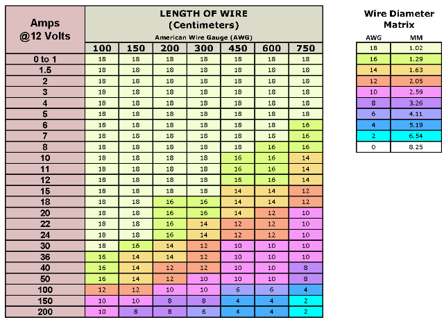
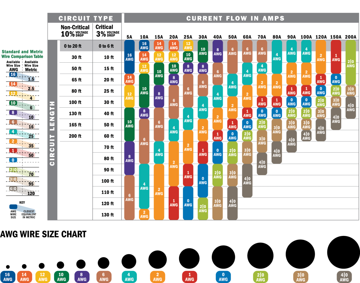
AWG (American Wire Gauge) diameter of elctrical wires
| WIRE SIZE (AWG) | WIRE DIA. INCHES | WIRE DIA. mm | AREA, CIRCULAR MILLS | FT/OHMS (Standard Annealed Copper ) |
| 40 | 0.003 | 0.08 | . | . |
| 38 | 0.004 | 0.10 | . | . |
| 36 | 0.005 | 0.13 | . | . |
| 34 | 0.006 | 0.16 | . | . |
| 32 | 0.008 | 0.20 | . | . |
| 30 | 0.010 | 0.26 | . | . |
| 28 | 0.013 | 0.32 | . | . |
| 26 | 0.016 | 0.41 | . | . |
| 24 | 0.020 | 0.51 | . | . |
| 22 | 0.025 | 0.64 | 642.4 | 61.95 |
| 20 | 0.032 | 0.81 | 1,022 | 98.5 |
| 18 | 0.040 | 1.02 | 1,624 | 157 |
| 16 | 0.051 | 1.29 | 2,583 | 249 |
| 14 | 0.064 | 1.63 | 4,107 | 396 |
| 12 | 0.080 | 2.05 | 6,530 | 630 |
| 10 | 0.102 | 2.59 | 10,380 | 1,001 |
| 8 | 0.129 | 3.26 | 16,510 | 1,592 |
| 6 | 0.162 | 4.12 | 26.250 | 2,531 |
| 4 | 0.204 | 5.19 | 41,740 | 4,025 |
| 2 | 0.258 | 6.54 | 66,370 | 6,400 |
| 1 | 0.289 | 7.35 | . | . |
| 1/0 | 0.324 | 8.25 | 105,500 | 10,180 |
| 2/0 | 0.365 | 9.27 | 133,100 | 12,830 |
| 3/0 | 0.410 | 10.40 | 167, 800 | 16,180 |
| 4/0 | 0.460 | 11.68 | 211,600 | 20,400 |
| 250MCM | 0.500 | 12.70 | . | . |
| 300MCM | 0.540 | 13.72 | . | . |
| 350MCM | 0.590 | 14.99 | . | . |
| 400MCM | 0.630 | 16.00 | . | . |
| 500MCM | 0.700 | 17.78 | . | . |
Resistors
Diagram of resistors colors meaning.
Gpio

Gpio 40 pins colored with names and numbers
Cross Reference AWG to MM2
| AWG | mm2 |
|---|---|
| 30 | 0.05 |
| 28 | 0.08 |
| 26 | 0.14 |
| 24 | 0.25 |
| 22 | 0.34 |
| 21 | 0.38 |
| 20 | 0.50 |
| 18 | 0.75 |
| 17 | 1.0 |
| 16 | 1.5 |
| 14 | 2.5 |
| 12 | 4.0 |
| 10 | 6.0 |
| 8 | 10 |
| 6 | 16 |
| 4 | 25 |
| 2 | 35 |
| 1 | 50 |
| 1/0 | 55 |
| 2/0 | 70 |
| 3/0 | 95 |
| 4/0 | 120 |
| 300MCM | 150 |
| 350MCM | 185 |
| 500MCM | 240 |
| 600MCM | 300 |
| 750MCM | 400 |
| 1000MCM | 500 |
Crimp Gauge
NOTE: FACTIONAL NUMBERS INDICATE CRIMPED RING
TERMINALS – DECIMALS INDICATED SOLDER DIPPED AND PUNCH.
| CRIMPS FOR STUD SIZES | RING TERMINAL | TC | NPC | NPS | AVAILABLE PUNCH SIZES FOR TYPES “A” & “D” Attn: These are hole sizes – one size over stud size recommended. |
| . | . | . | . | . | .062 (1/16) |
| . | . | . | . | . | .078 (5/64) |
| . | . | . | . | . | .093 (3/32) |
| #4 | YES | YES | . | . | .109 (7/64) |
| . | . | . | . | . | .125 (1/8) |
| #6 | YES | YES | YES | YES | .140 (9/64) |
| .. | . | .. | .. | . | .156 (5/32) |
| #8 | YES | YES | YES | YES | .171 (11/64) |
| . | . | . | .187 (3/16) | ||
| #10 | YES | YES | YES | YES | .203 (13/64) |
| . | . | . | . | . | .218 (7/32) |
| . | . | . | . | . | .234 (15/64) |
| . | . | . | . | . | .250 (1/4) |
| 1/4 | YES | YES | YES | YES | .265 (17/64) |
| . | . | . | . | . | .281 (9/32) |
| . | . | . | . | . | .296 (19/64) |
| . | . | . | . | . | .312 (5/16) |
| 5/16 | YES | YES | YES | YES | .328 (21/64) |
| . | . | . | . | . | .343 (11/32) |
| . | . | . | . | . | .359 (23/64) |
| . | . | . | . | . | .375 (3/8) |
| 3/8 | YES | YES | YES | YES | .390 (25/64) |
| . | . | . | . | . | .406 (13/32) |
| . | . | . | . | . | .421 (27/64) |
| . | . | . | . | . | .437 (7/16) |
| 7/16 | YES | YES | . | . | .453 (29/64) |
| . | . | . | . | . | .468 (15/32) |
| . | . | .484 (31/64) | |||
| 1/2 | YES | YES | .. | .. | .500 (1/2) |
| 5/8 | YES | YES | . | . | NOT AVAILABLE |
| 3/4 | YES | YES | . | . | NOT AVAILABLE |
| 7/8 | YES | YES | . | . | NOT AVAILABLE |